Micro:bit Switch Access

Project Assistive technology

Computer devices and systems are vital for communication, education, employment, social interaction, and more. But more often than not, they can be inaccessible for people with disabilities. In this project, you will be designing a Bluetooth dual switch access device that enables people with disabilities to control mobile phones, tablets and computers – empowering individuals with physical and cognitive impairments to interact with technology, engage with their surroundings, and enhance their independence.

The process begins by building and learning about an example device called Tap, made up of a micro:bit microcontroller and a series of 3D printed components. Using your newly gained skills, you’ll move on to identify a real or hypothetical end user, and go through a creative journey to customise a dual switch specifically for their needs. Learn more about Tap in the video below and browse through the project sections to learn more about the journey.

*Special thanks to Loreto Dumitrescu for the project inspiration, Bill Siever for developing the BLE HID plugin for MakeCode, and DrakerDG for the micro:bit 3D model used throughout the project.

Criteria + Constraints

Toggle
  • The dual switch device must cater for a specific end user or a specific disability.
  • The dual switch device should only use 3D printed components and micro:bit controllers, with no soldering required. Multiple switch devices can be combined to increase functionality.

Project Difficulty

Toggle

This project is rated as advanced and is suitable for all those who have strong skills in 3D design and 3D printing, as well as basic skills with the BBC micro:bit.

Project Length

Toggle

The estimated project length is 8 hours, excluding any 3D printing time. This estimate includes designing and making 1 device plus time for testing and creating 1 improved version. The project can be run in shorter or longer periods of time depending on the number of iterations you choose to make. We recommend breaking the project up into multiple sessions (e.g. 8 x 1 hour sessions), which will allow you to 3D print necessary objects between sessions.

Equipment Required

Toggle

To participate in this project, you will require:

  • A laptop or computer with either Tinkercad or Fusion 360 , and MakeCode software (all free for educational and personal use).
  • A software or web application to create a digital portfolio. We recommend using Google Slides as we provide a portfolio template in this format.
  • Access to a 3D printer and 3D printing material.
  • A micro:bit v2 with battery pack (or multiple depending on your solution).
  • Rough modelling materials (e.g. clay, cardboard).
  • A mobile, tablet or computer device to pair with your dual switch.
  • A device to capture images of your design process to insert into the project portfolio.

Additional materials may be required depending on the design methods you use when developing your solution.

Project Portfolio

Toggle

The project will guide you in documenting your design process in a Google Slide portfolio format. The template portfolio can be accessed here. Simply create a copy of it and follow the guidance at the bottom of each project section to fill in the details. The template portfolio acts as a starting point and we encourage you to adapt the styling and content to your needs. Alternatively, feel free to create a portfolio from scratch in a software of your choice.

To begin your journey, you’ll be jumping straight in and building your own Tap device. By assembling and using an example device, you’ll better understand how adaptive switches work and the possibilities for customisation and innovation. Follow the steps below to build your switch. Then spend some time using the device on either a phone, tablet or Chromebook.

*Disclaimer – Due to the varying tolerances of 3D printers and material properties, we cannot guarantee the same functionality or tactile experience for each manufactured Tap device. If you have any issues with 3D printing or usage, please contact hello@weareprintlab.com and we will do our best to advise you with alternative print settings or design adjustments.

Visual of a 3D print bed with the 4 Tap components spread across it.

STEP 1: 3D Print Components

Download the STL files for Tap and 3D print them using the orientations shown in the above image. For the best tactile experience, we recommend using PLA material with a layer height of 0.1-0.15mm. Depending on your preferences, you may wish to 3D print the buttons separately in a different colour.

Download STL Files

A micro:bit plugged into a computer.

STEP 2: Upload Code to Micro:bit

Connect your micro:bit to a computer via USB connection. Then download and copy the HEX code file below and paste it onto the micro:bit, just like you would copy and paste a file onto a USB stick! This code enables Bluetooth connection and makes the A and B buttons send the 'tab' and 'enter' keyboard keys as outputs when pressed.

Download HEX Code

STEP 3: Assemble Case

Place the micro:bit inside the 3D printed cradle. Then place the A and B buttons on top of the existing switches. Finally, push the sliding lid onto the device and plug in the micro:bit's battery pack. Alternatively, use a USB type-B cable to power it from your device.

An iPad screen showing the bluetooth pairing sceen.

STEP 4: Connect Device

Ensure the micro:bit is powered up. Then go to your device and pair it in your bluetooth settings. The micro:bit will be named uBit.

An iPad screen showing a 'New Switch' popup.

STEP 5: Configure

The instructions in the below guide will show you how to set up ‘manual scanning’ on an iPad device with iOS. This will map the A button to the action ‘Move to Next Item’, and the B button to ‘Tap’. If you are using a different device, the steps will be similar, and the guide provides some external links with further information.

Download Guide

A Bluetooth dual switch access device being used on an iPad.

STEP 6: Use

When switch control is activated, you’ll see a blue border highlighting an item or a group of items. Pressing the A button will change what items are highlighted and once you reach the desired items, press the B button to select. To power off Tap, press and hold the flexure button on the underside of the device for 5 seconds. To power it up again, press the same button once.

When sharing open-source models like Tap, the documentation that comes with it can be just as important as the design itself. Documentation aims to support others not only in building and using models, but it provides key information for those who want to adapt or iterate upon the design. Check out the full documentation for Tap here. You will have seen much of the information on this page already but pay particular attention to the way everything is packaged together.

Project Portfolio

Toggle
  • Open up the project portfolio and enter your full name and the date on the title slide. If you haven’t already done so, you will need to go to ‘File > Make a Copy’ before you can begin editing the portfolio.
  • On Slide 2 (Switch Access), write a paragraph that explains what switch access is. Include information about how it benefits people with disabilities and the impact that open-source devices can have on society. Then use online research to insert a series of images that show examples (these do not have to be 3D printed).
  • On Slide 3 (Introducing Tap), use your own words to write a summary paragraph about Tap. Include information about what it is and how it works.

In this section, you’ll be learning how to use 3D CAD and Microsoft MakeCode to design the dual switch device you have been experimenting with. The purpose of this exercise is to provide you with the necessary skills to be able to customise the design to the needs of a specific end user later in the project.

Begin by opening up this Autodesk Fusion base file and participating in the tutorial below to design the case and buttons for the device. There are options for both voice over instructions and text-based instructions so simply pick your preferred method of learning. Alternatively, if you are a beginner or prefer using Tinkercad software, head to the next section for an alternative tutorial.

*Fusion tips: For this tutorial, you may find it easier to switch off the display grid in Fusion, and use the ‘Free Orbit’ navigation option. More information on free orbit vs constrained orbit navigation in this YouTube video by Tyler Beck.

Text-Based Tutorial

Toggle

Click the link below to watch a version of the tutorial with text-based instructions rather than a voice over.

Watch Tutorial

Challenge


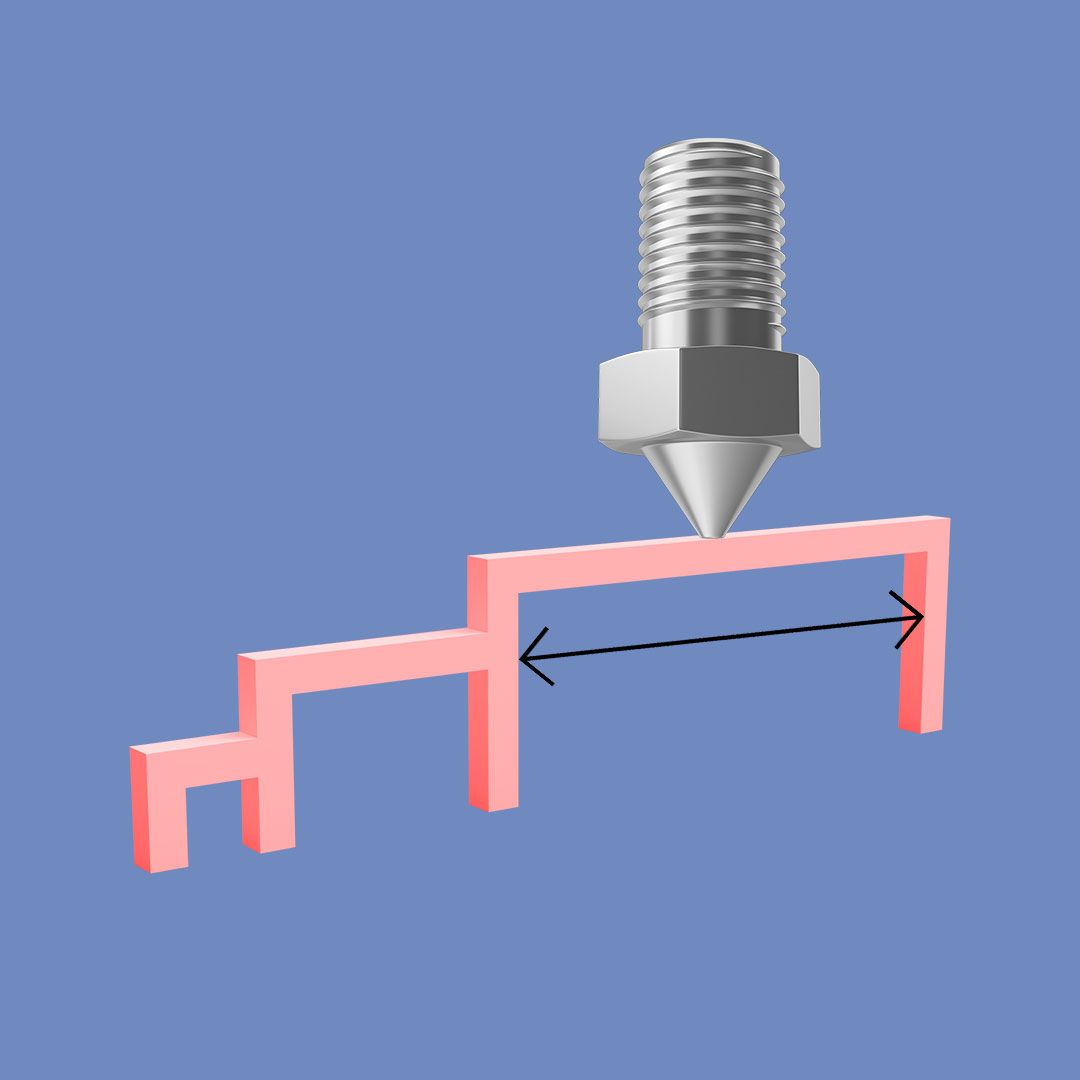
Since creating the tutorial, Tap has been updated with an additional design feature that we are challenging you to add in to your model! Depending on what 3D printer and material you use, the original design may result in the sliding lid being too loose. To combat this, we added in 2 small extrusions, which are shown in the below image. As the lid reaches the top of the cradle, it now meets 2 parts on each side (highlighted below), which stick out and apply tight friction to keep the lid in place during use. We call these parts ‘bumps’, and the distance they stick out is 0.4mm from the original design. See if you can add these, or similar features, into your design.


A before and after visual of Tap's sliding mechanism. The after version has 2 extra extrusions that apply friction when the lid is pressed on.

The video below is an alternative tutorial for beginners or users of Tinkercad. If you’ve already completed the Fusion tutorial, please skip this section and head to the MakeCode tutorial.

The tutorial will guide you in designing a simplified version of Tap, which uses a single button piece. If the left half is pressed, the A button is activated, and if the right half is pressed, the B button is activated. To participate in the tutorial, open this Tinkercad base model and follow the video instructions.

Text-Based Tutorial

Toggle

Click the link below to watch a version of the tutorial with text-based instructions rather than a voice over.

Watch Tutorial

The 3D CAD workflow is the most complex part of creating the dual switch access device, whereas the code for the micro:bit is super simple thanks to the amazing MakeCode extension built by Bill Siever. Follow the short MakeCode tutorial below to learn how to code the device. As you will see, we have included audio outputs in the code, whereas the original Tap does not include these. Once you have completed the tutorial, try downloading the code to your Tap device to see the differences in action.

Text-Based Tutorial

Toggle

Click the link below to watch a version of the tutorial with text-based instructions rather than a voice over.

Watch Tutorial

Before you move on to designing a device for a specific end user, we’re going to look at just a few ways in which you can customise the switch. Later in the project, you can refer back to these ideas to see if any are relevant to the needs of your end user.

A mute icon next to a raise hand icon.

Functionality

Tap's original functionality is based on mapping the buttons to 'Move to next item' and ' Tap' for switch control. However, there's so much more you can do using the BLE HID plugin for MakeCode. One example is to use the buttons to send keyboard shortcuts/macros for applications like Microsoft Teams - allowing users to easily activate popular functions like accept call, mute, raise hand etc. Not only can this support people with disabilities, but it can create efficient workflows for anyone!

A Bluetooth dual switch access device with textured buttons.

Colour + Texture

The beauty of 3D printed devices is that we can easily and cost-effectively customise the form within a matter of hours. This might include incorporating the end user's favourite colours or applying textures to enhance the tactile experience.

A Bluetooth dual switch access device with play and pause buttons.

Tactile Graphics

Tactile graphics can also be used to signify and remind users of button actions. These might include media graphics such as play/pause. Alternatively, they can be used to add playful aesthetic touches, such as animals or cartoon characters.

A Bluetooth dual switch access device with figner groove buttons.

Form

People with certain disabilities may prefer completely different forms to regular buttons. For example, they may be better suited to grooves where their fingers rest.

Graphic of a wheelchair with the armrest highlighted.

Mounting

In addition to being used on a flat desk surface, Tap's basic rectangular shape easily allows 'add-ons' to be created. These might include mounting solutions for wheelchairs, bed frames, walls etc.

A screen showing MakeCode software and the code for a bluetooth dual switch access device.

Inputs + Outputs

MakeCode's vast block library enables you to explore a whole range of functions for Tap. This might include different sound outputs when buttons are pressed, or you can even get creative and see if you can include additional 'buttons' through sound inputs.

It’s now time to use everything you’ve learned to design your own switch device for an end user of your choice. This might be a customised version of Tap, or a completely new design. Follow the guidance below to move through the full creative process. Remember to document everything you do in the form of images and notes, so you can assemble them into your portfolio at the end.

*The following instructions are just one of many ways in which you might approach the design process. If you’d like to adapt the project or challenge yourself to take an alternative approach, feel free to explore the Design Method Toolkit and use different methods to those stated in this project.

A hand holding on to a wrist.

STEP 1: Identify End User

The first step is to select an end user to design for. This might be someone you know who has a disability, or alternatively, you may wish to choose a specific disability to design a solution for. Either way, perform in-depth research on the disability and pay particular attention to the resting hand positions and comfortable range of motion.

Part of a storyboard that shows the workflow of someone using Microsoft Teams.

STEP 2: Storyboard Activities

Work with your end user to identify specific tasks in their daily routine where a dual switch device may be helpful. Then create storyboards that map out exactly how your end user performs these activities, or how they wish they could perform the activities. For example, each step to turn on their tablet and play music. Then use your storyboards to create a list of design criteria to follow in the next stages of design. Think of the criteria as a list of 'must-haves' for your device. If you are designing for a specific disability rather than a real end user, use hypothetical scenarios.

View Storyboard Method

STEP 3: Real-time Prototyping

Select the most impactful storyboard activity and use the real-time prototyping method to mock up some rough models that can improve the experience for it. Alternatively, see if you can think of ways that your device can be used for multiple activities - this might involve creating multiple devices. If you are adapting Tap, consider removing the buttons from the device and creating rough models for new buttons that better suit your end user.

View Real-Time Prototyping Method

A 3D CAD screenshot of a joystick button device.

STEP 4: 3D Printed Prototype

By selecting your most promising real-time prototype, or by combining features of different ones, bring your first high-fidelity prototype to life using 3D CAD and 3D printing! In addition to the physical design, create the necessary code for your micro:bit using MakeCode software. If you are adapting Tap, the Fusion and Tinkercad files are available below to save you time recreating every component.

Download Tap Design Files

A 3D printed dual switch device with a joystick button attachment.

STEP 5: Test

Begin by testing your initial prototype yourself, and note down any thoughts, comments and improvements. Then work with your end user (or volunteers if you are designing for a specific disability) and continue testing. Ensure you thoroughly test the activity the device was intended for and gather feedback in the form of an interview, observations, a survey, or another relevant method.

A set of 3D printed Bluetooth dual switch access devices.

STEP 6: Iterate

Develop an improved iteration of your switch device (or devices) and repeat the testing process. Continue this cycle until you reach a stage where you and your end user are happy. If you'd like to take the project further, use Tap's documentation as inspiration to develop your own maker guide, images etc, and release your design open-source on sites like Makers Making Change or Tikkun Olam Makers.

Project Portfolio

Toggle
  • On Slide 5 (The End User), write a paragraph about your end user or the specific disability you are designing for. Include useful information such as their age, occupation and comfortable range of motion. The insert images of your end user. This might include visuals showing their range of motion.
  • On Slide 6 (Activity 1), write a paragraph about the first common activity you storyboarded. Discuss the steps taken in the journey, as well as the emotions felt by the end user throughout. Then insert an image of your storyboard.
  • On Slide 7 (Activity 2), write a paragraph about the second common activity you storyboarded. Discuss the steps taken in the journey, as well as the emotions felt by the end user throughout. Then insert an image of your storyboard.
  • On Slide 8 (Design Criteria), write a sentence about the design criteria you developed based on findings from the empathy phase. Then list them in a bulleted format.
  • On Slide 9 (Real-Time Prototyping), write a paragraph about your real-time prototyping models. Explain how you created them, what changes you made along the way, and why you made the changes. Then insert a series of images showing the prototypes.
  • On Slide 10 (Initial High-Fidelity Prototype), write a paragraph about the process you took to go from rough model to initial 3D printed prototype. Include information about its design and features. Then insert images of the prototype, as well as a screenshot of the CAD process.
  • On Slide 11 (Testing + Iteration), write a paragraph about your testing and iteration phase. Include information about your testing strategy, the insights you gained, and how you applied them to create improved designs. Then insert images of the testing and iterating phase.
  • On Slide 12 (Final Product), write a paragraph about your final product. Include a short reflection and highlight any improvements you’d make if you were to take it further. Then insert a final image and 2 additional final images on Slide 13.