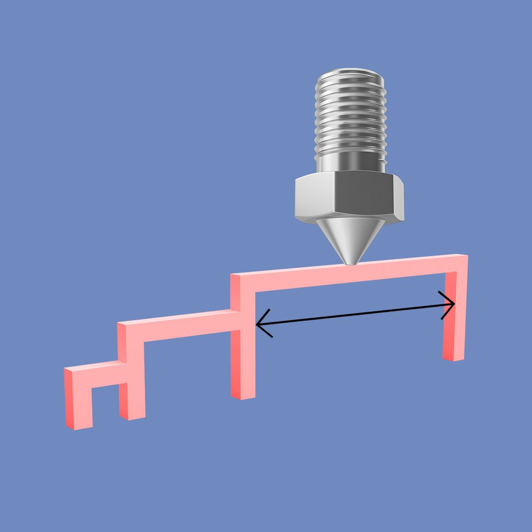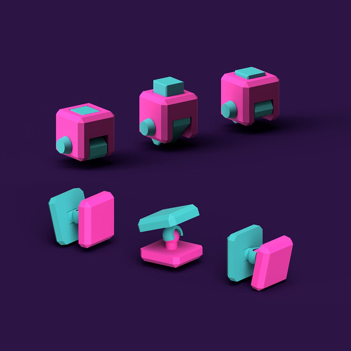
8. Mechanism Cubes

Course Mini Courses

In this intermediate-advanced mini course, you’ll be introduced to the fascinating world of 3D printed mechanisms. The creative learning resources will teach you how to add connections and movement to your 3D models – unlocking new and innovative design possibilities. New mechanisms will be added to the course throughout the year, so be sure to check back here regularly. At the end of the course is a quiz, and if you achieve over 70%, you can download a certificate!


Each section of the mini-course focuses on a different mechanism and comes with a range of resources to help you master it. Although you are free to pick and choose how you use the resources, we recommend following the below workflow for each mechanism.

1. Introduction Video

Toggle

Begin by watching the mechanism introduction video to give you a brief overview of what the mechanism is and how it works.

2. Explore Model Files

Toggle

Download the model files folder for the mechanism. Some mechanisms have separate model files (1 designed in Tinkercad, 1 designed in Fusion 360). In this case, you should select the file set that corresponds to the software you generally use. Once downloaded, open up the Tinkercad/Fusion 360 design file and explore its geometry to gain a basic understanding of its design.

If choosing the Fusion 360 model sets, you’ll notice there are 2 files for each mechanism. Use the one with ‘Joints’ in the title when exploring. This will allow you to click and drag on the model to digitally simulate its movement.

3. 3D Print

Toggle

After exploring the digital model files, 3D print the STL files (included in the model file folder). Each section of the learning platform shows an illustrated graphic of the best 3D printing orientation for the mechanism. Once 3D printed, play and learn from the physical model – to gain an understanding of the movement and relationship between components.

Please note that all 3D printers have different tolerances and if the included STL files do not print as intended, you may need to adjust dimensions/clearances in the design files to suit your specific machine.

4. Tutorial

Toggle

With a general understanding of the mechanism in place, participate in the 3D design tutorial. As with the model files, some mechanisms come with both Tinkercad and Fusion 360 tutorials. There are also options for both voice over instructions and text-based instructions so simply pick your preferred method of learning.

5. Experiment

Toggle

At this stage, you should have the skills and knowledge to use the mechanism in your own creative work. You may wish to check out some of the suggested challenges at the bottom of the learning platform, or you may wish to incorporate the mechanism into a completely new design.

Tinkercad Model Files

The Tinkercad hinge cube consists of 2 main components that are connected with a third axle component. Once 3D printed, simply place the 2 box halves together and slide the axle through the holes to complete the assembly.

Download Model Files

Tinkercad logo on top of white box that reads 'Hinge Mechanism Cube - with voice over instructions'.

Tinkercad Tutorial

A step-by-step tutorial to design a hinge mechanism cube in Tinkercad - with voice over instructions.

Watch Tutorial

Fusion 360 logo on top of white box that reads 'Hinge Mechanism Cube - with voice over instructions'.

Fusion 360 Tutorial

A step-by-step tutorial to design a parametric, print-in-place hinge mechanism cube in Fusion 360 - with voice over instructions.

Watch Tutorial

Fusion 360 Model Files

The Fusion 360 hinge cube is made up of only 2 components as the bottom box half has an axle built into its form. The model also prints in place with no assembly required. During the 3D printing process, the axle ‘bridges’ through the hinge of the top box half.

Download Model Files

Text-Based Tutorials

Toggle

If you prefer text based video tutorials to voice overs, check out the below links:


Tinkercad Tutorial with Text Instructions Fusion 360 Tutorial with Text Instructions


Challenges

Toggle

Here are some activities you might want to try after completing the tutorial:

  • Can you create voids in the cube to turn it into a storage box?
  • Can you change the limits of the hinge rotation?
  • Can you incorporate another hinge somewhere in the design?

Tinkercad Model Files

The Tinkercad screw cube consists of 2 box halves – 1 with a female thread and the other with a male thread. Depending on your 3D printer’s tolerances, you may feel some friction when screwing the 2 components together. However, after a few twists, the threads should run smoothly against each other.

Download Model Files

Tinkercad logo on top of white box that reads 'Screw Mechanism Cube' - with voice over instructions'.

Tinkercad Tutorial

A step-by-step tutorial to design a screw mechanism cube in Tinkercad - with voice over instructions.

Watch Tutorial

Fusion 360 logo on top of white box that reads 'Screw Mechanism Cube' - with voice over instructions'.

Fusion 360 Tutorial

A step-by-step tutorial to design a parametric, screw mechanism cube in Fusion 360 - with voice over instructions.

Watch Tutorial

Fusion 360 Model Files

The Fusion 360 screw cube also consists of 2 box halves - 1 with a female thread and the other with a male thread. If you would like to edit the scale or clearances of the cube, you can open the ‘Parameters’ tool in Fusion 360 and change the values. For example, if the screw feels tight to turn, consider increasing the tolerance parameter. You’ll learn more about Fusion 360’s parameter settings in the tutorial so be sure to check that out.

Download Model Files

Text-Based Tutorials

Toggle

If you prefer text based video tutorials to voice overs, check out the below links:


Tinkercad Tutorial with Text Instructions Fusion 360 Tutorial with Text Instructions


Challenges

Toggle

Here are some activities you might want to try after completing the tutorial:

  • Can you create a series of cubes with different sized threads?
  • Can you create a nut and bolt?
  • Can you find an object with a thread and design an attachment for it? For example, turn a water bottle into a plant watering can.

Tinkercad Model Files

The Tinkercad ball and socket cube is made up of a ball component and a socket component. Once 3D printed, simply push the ball into the socket. Due to the thin form of the socket, it will flex slightly during assembly, before wrapping back around the ball.

Download Model Files

Tinkercad logo on top of white box that reads 'Ball + Socket Mechanism Cube - with voice over instructions'.

Tinkercad Tutorial

A step-by-step tutorial to design a ball and socket mechanism cube in Tinkercad - with voice over instructions.

Watch Tutorial

Fusion 360 logo on top of white box that reads 'Ball + Socket Mechanism Cube - with voice over instructions'.

Fusion 360 Tutorial

A step-by-step tutorial to design a parametric, ball and socket mechanism cube in Fusion 360 - with voice over instructions.

Watch Tutorial

Fusion 360 Model Files

The Fusion 360 ball and socket cube is also made up of a ball component and a socket component. The STL files include a socket with no clearance (for a tighter fit) and another with a 0.1mm clearance (for a looser fit). You can also change the tolerance parameter in the Fusion 360 file to experiment further. You’ll learn more this in the tutorial so be sure to check that out.

Download Model Files

Text-Based Tutorials

Toggle

If you prefer text based video tutorials to voice overs, check out the below links:


Tinkercad Tutorial with Text Instructions Fusion 360 Tutorial with Text Instructions

Challenges

Toggle

Here are some activities you might want to try after completing the tutorial:

  • Can you design a series of ball and socket mechanism cubes that have different range of motions?
  • Can you change the mechanism to be tighter or looser?
  • Can you create a model that locks the movement of the ball and socket at set positions? For example, an adjustable phone or camera mount.

Tinkercad Model Files

The Tinkercad rack and pinion cube consists of 4 components - the cube, rack, pinion and an axle that connects the gears. Once 3D printed, place the rack at the bottom of the cube. Then place the gear on top and slide the axle through from the outside of the cube.

Download Model Files

Tinkercad logo on top of white box that reads 'Rack and Pinion Mechanism Cube - with voice over instructions'.

Tinkercad Tutorial

A step-by-step tutorial to design a rack and pinion mechanism cube in Tinkercad - with voice over instructions.

Watch Tutorial

Fusion logo on top of white box that reads 'Rack and Pinion Mechanism Cube - with voice over instructions'.

Fusion 360 Tutorial

A step-by-step tutorial to design a rack and pinion mechanism cube in Fusion 360 - with voice over instructions. *Please note that you will be required to install the GF Gear Generator plugin to Fusion. The download link can be found in the next section down on this page.

Watch Tutorial

Fusion 360 Model Files

The Fusion rack and pinion cube works in the exact same way as the Tinkercad model and also consists of 4 components that need to be assembled. All components can be 3D printed without support material, as shown in the graphic above.

Download Model Files

GF Gear Generator Plugin

Toggle
  • To download the GF Gear Generator plugin required for the Fusion tutorial, click here.
  • Although not required for the tutorial, here is an in-depth overview of the plugin in case you want to experiment further with its capabilities.

Text-Based Tutorials

Toggle

If you prefer text based video tutorials to voice overs, check out the below links:


Tinkercad Tutorial with Text Instructions Fusion 360 Tutorial with Text Instructions

Challenges

Toggle

Here are some activities you might want to try after completing the tutorial:

  • Can you create something that stops the rack from falling out of the cube?
  • Can you redesign the mechanism cube with a different number of teeth for the rack and pinion gears?
  • Can you create another mechanism that replaces the rack with another cylindrical gear?

Tinkercad Model Files

The Tinkercad cam and follower cube consists of 4 components – the cube, cam, follower and an axle. Once assembled, the cam is rotated using the protruding axle, which in turn pushes the follower upwards in a vertical motion.

Download Model Files

Tinkercad logo on top of white box that reads 'Cam and Follower Mechanism Cube - with voice over instructions'.

Tinkercad Tutorial

A step-by-step tutorial to design a cam and follower mechanism cube in Tinkercad - with voice over instructions.

Watch Tutorial

Fusion logo on top of white box that reads 'Cam and Follower Mechanism Cube - with voice over instructions'.

Fusion 360 Tutorial

A step-by-step tutorial to design a parametric cam and follower mechanism cube in Tinkercad - with voice over instructions.

Watch Tutorial

Fusion 360 Model Files

The Fusion rack and pinion cube works in the exact same way as the Tinkercad model and also consists of 4 components that need to be assembled. However, the Fusion model comes with the added benefit of being parametric – allowing you to open the f3d file and edit the ‘boxsize’ parameter to change the entire cube’s size.

Download Model Files

Text-Based Tutorials

Toggle

If you prefer text based video tutorials to voice overs, check out the below links:


Tinkercad Tutorial with Text Instructions Fusion 360 Tutorial with Text Instructions

Challenges

Toggle

Here are some activities you might want to try after completing the tutorial:

  • Can you experiment with different shaped cams and document their impact on the mechanism?
  • Can you redesign the cube to reduce or increase the follower’s vertical motion?
  • Can you add electrical components to automatically rotate the axle without manually turning it?

We hope you’ve enjoyed the Mechanism Cubes course, and we look forward to sharing more soon! In the meantime, we’d like to showcase an example of what can be done with 3D printed mechanisms. Introducing BoxBot B-01 – the first in a series of print-in-place robot figurines that fold up into cubes. The model features 10 3D printed hinges that operate 4 moveable legs and 2 cannons that fold out from the robot’s main body. Check out both the assembly and design process videos below!

A 3d printed robot figure folded up into a cube.

In addition to being print-in-place with no support material, B-01 was designed parametrically in Autodesk Fusion, which means you can open up the f3d model file and change the ‘boxsize’ parameter to adjust its overall size to whatever you please. Download the files for free from our profiles on Makerworld and Printables.


Download Files

Our Latch mechanism cube resources are in development and will be released soon.


A row of latch mechanism cubes.

Welcome to the Mechanism Cubes assessment quiz. Enter your name below and answer the multiple choice questions. If you are a student under 16 and do not have the parental consent form signed and sent to hello@weareprintlab.com, please use a nickname.


You are required to achieve 70% or above to be able to obtain a certificate. If you score under this, simply refresh the page and try again. Good luck!

Name
Doors, fuel caps and laptops use which mechanism to open and close:

The pivot point of the hinge cube is located...

If you design and 3D print a screw thread with zero clearance between the threads, what is likely to happen?

A nut and bolt is an example of which mechanism?

The joints in your shoulder that allow for rotational movement resemble which mechanism?

Is this statement true or false? - When assembling the ball and socket cube, the walls of the socket component must flex outwards in order to allow the ball to fit within the socket.

Rack and pinion mechanisms convert...

In a rack and pinion mechanism, the pinion refers to the...

Which of the following uses a cam and follower mechanism?

In a cam and follower mechanism, the cam refers to...